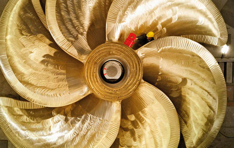
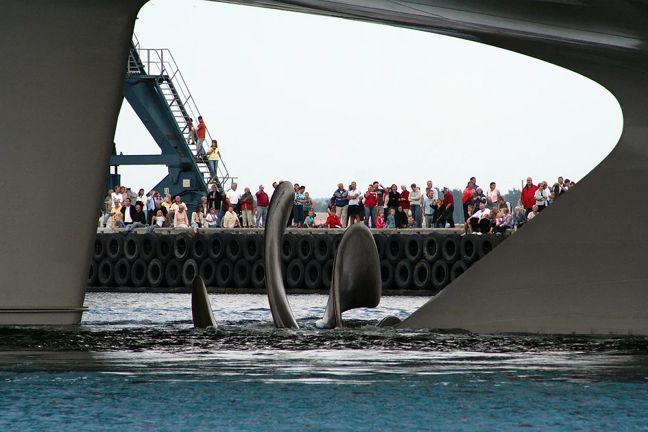
Who else has ever stood next to the stern of a docked ship and immediately tried to catch a glimpse of the propeller through the water? Or even better, who has ever watched as unloaded cargo ships slowly move along a river with their propeller rotating and sticking halfway out of the water, due to a smaller draft? There is just something terribly exciting about seeing a ship’s propeller come out of the water. It almost seems indecent, like something that is supposed to stay hidden. But what makes a ship’s propeller so fascinating? Perhaps it is the fact that you cannot see it when it is submerged, but you know it is always there. Or perhaps it is the fact that it can be dangerous and yet powerful when operating, making it both scary and captivating at the same time.
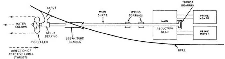
Ship propellers (often referred to as ship screws) are by far the most widely used propulsion type for ships today, arranged either in a traditional propeller shaft configuration or a podded-thruster configuration. Propellers can be either fixed or have variable pitch, but both of these types operate on the same principle. In addition to these, there are several special types of propellers, such as Voith Schneider or Kirsten-Boeing propellers, which operate on a different principle and will be discussed separately in a future post.
The main task of the propeller is to move the ship forward by converting rotational power into thrust. Thrust is created from a difference in pressure between the front and back surfaces of the propeller’s blades. This difference allows for water to be accelerated. This concept can more easily be understood by imagining a screw turning thought wood. A ship’s propeller works in the same way, but it is turning through water.
In addition to moving a ship forwards, propellers also affect maneuverability, noise and vibrations, parts of the ship’s machinery and drive elements. Since the propeller greatly influences the shape of the ship’s stern, it must always be considered in connection with the stern and its attachments.
There are two main perspectives from which the functioning of the propeller can be looked at: momentum theory and blade element theory. Momentum theory looks at how the propeller creates thrust by accelerating water to the rear. The change of the momentum corresponds to the propeller thrust. In blade element theory, the efficient operation of a propeller is considered in terms of its blades. This model explains the propeller’s effect on the individual sections of the blades. Aspects of both theories need to be taken into account when choosing the most efficient propeller design.
Propeller and Hub Diameter
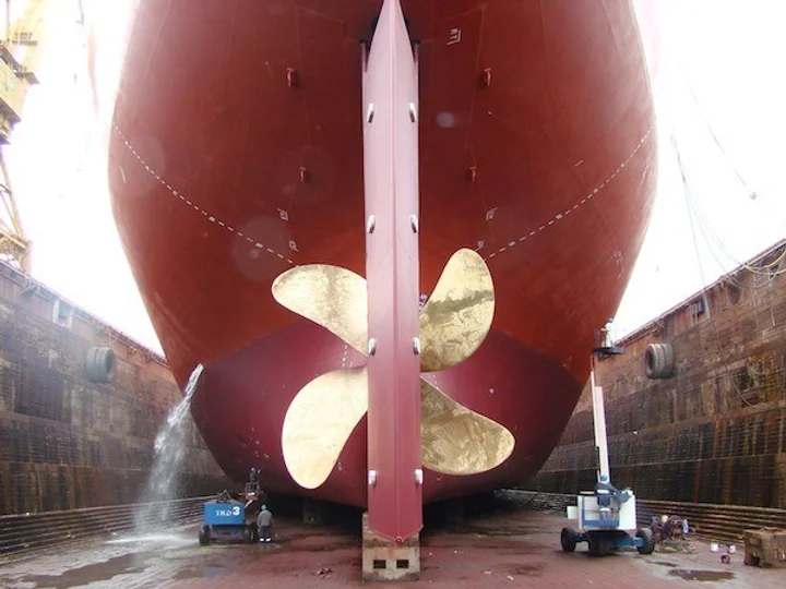
The most important propeller characteristic, crucial for the efficiency of the propeller, is its diameter D. The efficiency of the propeller increases with the size of the diameter. This comes from the principle that to achieve the necessary momentum for the thrust, it is better to accelerate a larger amount of water at a lower rate than to accelerate a smaller amount of water at a higher rate. Hence, the choice is usually in favor of the largest possible propeller.
The opposite is true for the hub diameter of the propeller – it should be as small as possible, as the hub itself does not contribute to the action of the propeller. For fixed-pitch propellers the hub diameter should be around 18% to 20% of the propeller diameter for reasons of strength. For variable-pitch propellers, the hub diameter should be around 30% to 34% of the propeller diameter.

Of course, the propeller cannot be arbitrarily large, and certain boundary conditions which may limit the diameter exist. Firstly, pressure fluctuations and noise from the propeller are transferred to the ship though the outer plating of the ship’s hull. Therefore, there is a minimum distance required between the propeller and the outer shell plating of the ship. As a general rule, the minimum clearance from propeller to plating should not be less than 0.3 times the propeller diameter (0.3D). If the distance is significantly less, pressure fluctuations may lead to damages in the plating which are very costly to repair. In some exceptional cases, if a very good slipstream exists, the distance can be reduced to 0.27D-0.28D.

Secondly, it is generally assumed that the propeller should not reach below the baseline of the hull so that in case the ship touches the ocean floor or a reef in shallow waters, the propeller will not be the damaged. Thirdly, the draft of the ship could also be a limiting factor to propeller diameter. If possible, the propeller should not come out above the water as this can cause air ingress. When the propeller blade dives back into the water, it draws air with it, causing the buoyancy on the blade to collapse. This has to be avoided at all costs, and therefore the height of the stern wave must also be considered. Last but not least, a problem could also arise in ships with smaller 2-stroke engines (around 5000 kW), where the engine speed is relatively high. At such speeds, a large propeller might not operate well even if the pitch is reduced, in which case a smaller propeller with a higher pitch might provide better efficiency.
Number of Blades
There are several criteria for the choice of the number of propeller blades. In terms of efficiency, the lowest number of blades possible is preferred because the individual blades affect each other, which can reduce their effect. This can be better understood when looking at an analogous example from aviation. If you consider the wings of a biplane, the wings are arranged one above the other so that the suction side of the lower wing is below the pressure side of the upper wing. The result of this is that the effect on each wing respectively is reduced and the total lift created is less than twice the effect of the single wing. The same holds true for a larger number of blades in a ship propeller.
On the other hand, a higher number of blades may be preferred when vibrations are a factor, as the wake in which the propeller operates is not uniform. The fewer the blades, the higher the load on each individual blade and the higher the torque and thrust fluctuations transmitted on to the shaft. The same applies to the pressure fluctuations on the outer plating of the stern.
In some cases the number of blades is also coordinated with the number of cylinders of the main engine. In many cases, the excitation frequency of the propeller and engine should not coincide in order to avoid resonance. In other words, the number of blades and the number of cylinders should not be integral multiples of a number, because the excitation of the propeller is directly related to its number of blades and the excitation of the engine is directly related to its number of cylinders. To give an example, a propeller with four blades is not recommended for an 8-cylinder engine, whereas a five bladed propeller is recommended for a 6-cylinder engine.
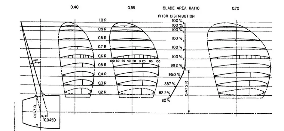
Blade Area Ratio
The blade area ratio AE/A0, is the ratio between the total area of the blades, divided by the total area of the propeller. For efficiency and cost reasons, this ratio should be kept as low as possible. However, propellers must have a certain minimum surface area, otherwise loads on the individual blades may become too big and extreme pressures on the blades may lead to excessive cavitation. This minimum area requirement is dependent on the specific thrust load of the propeller. For highly loaded propellers, which have a small diameter and a high thrust, a larger blade area ratio may improve efficiency while maintaining the same thrust, through a more favorable distribution of the local pressure on the blade. For variable-pitch propellers, the blade area ratio is limited by the fact that when adjusting the blades they may collide with each other and should therefore be no more than around 0.7. For fixed-pitch propellers, the ratio may even reach above 1 in some cases.
Pitch
Simply put, pitch is the distance a point on the propeller travels through the water when the propeller spins around its axis for a whole revolution. This means that in theory, a propeller with a pitch of 30cm, for example, would cover a distance of 30cm in one revolution. The pitch is measured on the surface of the blade, usually on the pressure side.
There are two types of pitch: constant or progressive. Constant pitch remains the same from the leading edge to the trailing edge or in other words, it corresponds to a profile without a curvature of the pressure-side surface. Progressive pitch starts out low at the leading edge and slowly increases towards the trailing edge. In propellers with progressive pitch, the average value of the pitch is calculated. Progressive pitch results in more thrust at medium and high power.

The propeller pitch exerts a strong influence on speed and torque and, thus, on the choice of engine and transmission. For the efficiency of the propeller, a higher pitch is generally preferred. This is because propellers with a high pitch are usually operated at low rotational speeds to produce the required thrust. Low speeds also mean less efficiency losses due to friction.
It also needs to be considered that a high pitch, especially in the blade tip area and in the hub area, has a negative impact on cavitation behavior around the propeller and these areas of the propeller have a pronounced pitch reduction.
Rake
The rake of a propeller blade is the degree to which the blade leans backwards (aft rake) or forwards (forward rake) in relation to the propeller hub. Rake can be either flat or progressive. Flat rake means that the blade is tilted to the same degree along its entire length whereas progressive rake means that the angle between the hub and the blade increases along the blade towards its tip.
Rake is important as it allows for a greater clearance between the propeller and the ship’s hull. If the tip of the propeller blade passes too close to the hull plating, vibrations may occur. These vibrations could potentially lead to poor operation of the propeller as well as to structural damage of the hull plating and the propeller blades.
Skew
Simply put, the skew of a propeller blade is the degree to which it is tilted to the side, when looking at it from the back. A more precise definition is provided by the Wärtsilä Encyclopedia of Marine Technology: the “skew angle of a propeller is the angle measured from ray “A” passing through the tip of the blade at mid-chord line to ray “B” tangent to the mid-chord line on the projected blade outline.” Skew can be either balanced or biased as seen in the picture below.

In both types, the aim of a skewed blade is to disperse local stresses, to avoid fluctuations in torque and thrust and to reduce noise and cavitation.
Blade Thickness Distribution
The radial distribution of the blade profile thickness is also crucial for a good propeller design. From a hydrodynamic point of view, a thin profile should be chosen, as it has a lower displacement resulting in less pressure fluctuations on the outer plating of the hull. However, thinner profiles are also more prone to cavitation around the leading edge of the blade, if the angle of attack is high enough.
For reasons of strength, thicker profiles are usually used in the area of the blade root. This is because the bending moment of the blade increases towards the root. On the other hand, if the root profile is designed too thick, cavitation at the root may occur. Therefore, the design should consider both the hydrodynamic, as well as the strength issues surrounding the propeller blades.
We have come a very long way since the first attempts in the field of propulsion and we owe today’s advanced propeller design to the many brilliant minds who worked on it over hundreds of years. That being said, we are still far from omniscient on the subject, so if you have any ideas how to improve a propeller’s design, please post them in the comments below!
The Shipyard