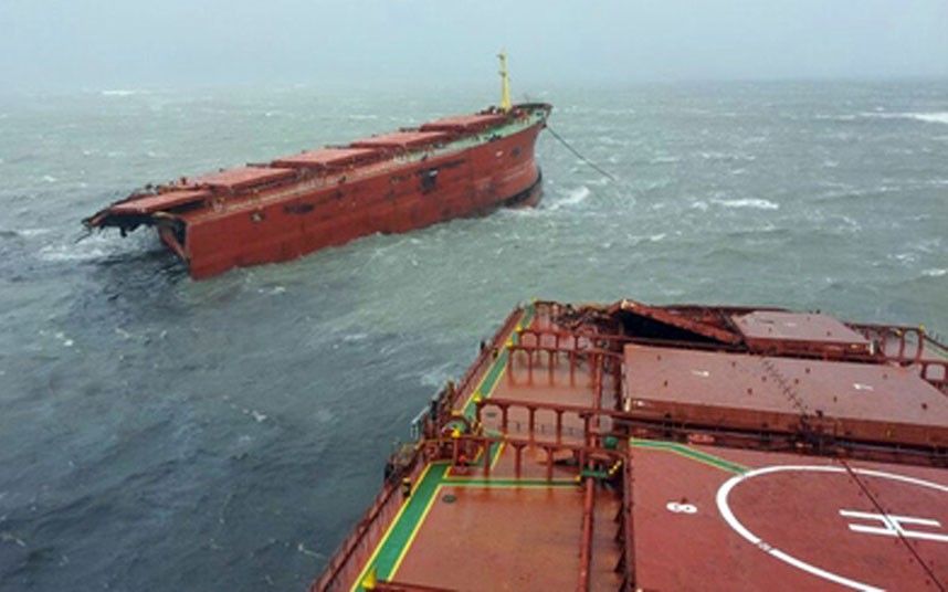
Structural failure of ship hulls has led to the loss of hundreds of vessels throughout history. As the scale of today’s bulk carriers becomes larger and the cargo they carry becomes more hazardous to the environment, structural integrity is more important than ever. It is therefore critical for engineers to understand the mechanisms causing these structural failures. Some of the most common causes for structural failure of a ship’s hull are imperfections in the ship’s structure leading to crack initiation, impurities in the steel of the hull plating weakening strength of the hull, built-in stresses inherited from a poor manufacturing process, and unexpected high stresses on the ship during cargo loading and while sailing through waves. Despite modern modelling techniques and software, the complex structure of the ship and the forces acting upon it, call for the consideration of a number of key factors to prevent the naval architect from over – or underdesigning a ship.
Stresses in Ships in Still Water
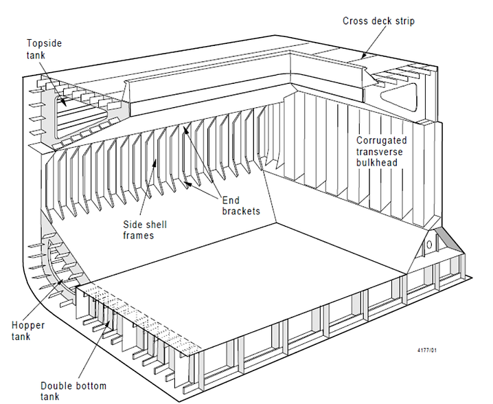
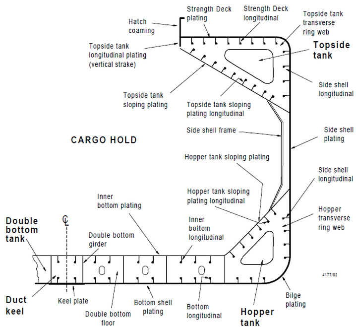
Ships floating in still water experience different stress conditions than those moving in open seas. When a homogeneous body of uniform cross-section and weight is floating in still water, at any section the weight and buoyancy forces are equal and opposite. In such a case, all forces are balanced and no deformation occurrs. A bulk carrier however, does not have an evenly distributed weight due to its structural and cargo distribution. It also does not have an evenly distributed buoyancy due to the fact that the cross-sectional area of the hull underwater is not the same along the whole length of the ship. While the overall buoyancy and weight of the ship are in balance, different sections of the ship experience a resultant force. This force is the result of a surplus load or buoyancy. Forces run up and down the hull of the ship which cause shear to the vertical plates of the hull and the hull girder as a whole. These forces are called vertical shear forces. The hull girder is composed of several key structural components including shell plating, transverse bulkheads and side shell or web frames.
A ship docked in still water can be compared to a simple beam with a box section. When overloaded at the ends of the ship, the ship will experience hogging. In this case, the deck surface on top of the ship will be in tension while the bottom surface of the hull will be in compression. When the load is distributed more towards the mid section of the ship, the ship will experience sagging. In this case the bottom of the hull experiences tension, whereas the surface of the deck is in compression. Hogging and sagging are the two types of bending moments experienced by ships floating in still water.
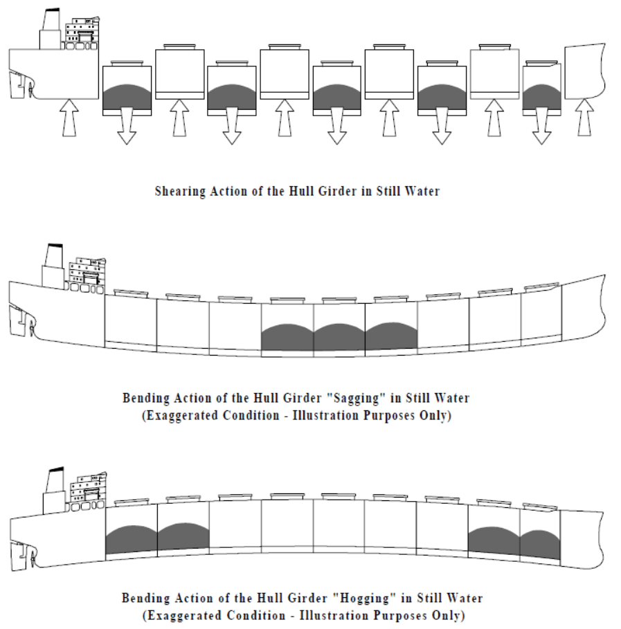
When the ship moves from hogging to sagging and vice versa, a middle stage exists in which the bottom and the deck surfaces are neither in tension nor in compression. This is known as the neutral axis, and can again be linked to basic beam theory. In a bending beam, the area furthest away from the neutral axis will experience the greatest stress. The larger the second moment of area value of a beam, the smaller the bending stress value becomes.
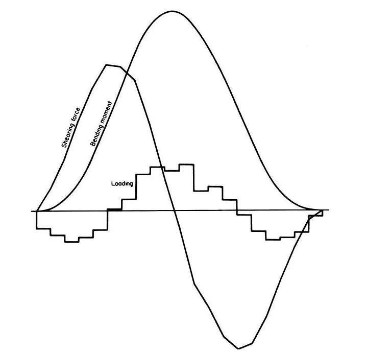
The maximum bending moment of a ship is typically at its midsection. The midsection is therefore used to calculate maximum permissible stresses and to include a safety factor. If the the bending stress exceeds the designed bending strength of the hull’s material, the hull structure will fail.
Forces on a Ship in a Seaway
Seagoing ships can encounter six different types of motions as seen in the picture below. In heavy seas, these motions lead to dynamic loads on the ship’s structure.

As waves pass along the ship, pressure fluctuations occur in the hull plating. This phenomenon is referred to as panting and particularly affects the fore end of the ship. Panting results in cyclical shearing and bending of the hull. In addition, when the ship is heaving and pitching strongly, the bow of the ship comes out of the water. When the ship slides down the wave, the bow slams back into the water, causing high loads onto the bow plating. This is referred to as pounding or slamming.
The effects of panting and slamming call for additional stiffening to the fore end of the ship to prevent structural failure. In addition, slamming may lead to sloshing of liquids within the ship’s holds and tanks. The sudden movement of these liquids from one side to the other, may cause damage to the ship’s structure from the inside.
Modes of Failure
From a structural analysis perspective, there are five main failure modes for ships: direct fracture, fatigue fracture, corrosion, instability and unacceptable deformation.
Direct Fracture
Direct fracture can occur when a section of the ship’s hull attains its ultimate shear, tensile or compressive strength. This can occur, for example, when the ship is sailing in extreme weather conditions or when it is loaded past its design load.
Fatigue
Fatigue is a very common mode of failure in structures which experience cyclic stresses. A crack may emerge in a weak spot of the structure and propagate with each new loading cycle. The process of crack propagation is accelerated in materials experiencing frequent loading and unloading cycles while being exposed to a corrosive environment, often leading to premature structural failure. This is of particular concern for ships as they float in a highly corrosive environment for an avarage life span of 20 years. Structures may fail due to fatigue at lower stresses than their yield levels. Research on fatigue in ships has shown that the avarage fatigue life for a cargo ship is approximately 20 million cycles. Engineering structures often have small cracks in them and function properly despite these cracks. However, it is key to monitor cracks and predict how far the crack can be permitted to grow without causing damage to the structure. Calculating the length at which a through thickness crack becomes critical, is crucial for the safety of a ship. If the ship is only exposed to the forces it was designed to withstand, the critical crack length will largely depend on the fracture toughness of the steel.
Corrosion
Corrosion is a a chemical process in which a material reacts to lose atoms to another material or substance. In the case of ships, salt water causes the steel of the hull and its paint coating to deteriorate over time, resulting in a thinner cross-section of the steel plates.
Ships are generally designed with excess material to their hull to account for the material they will lose due to corrosion over their expected life time. Corrosion is often investigated in relation to fatigue as it can enhance crack initiation and propagation.
Instability
Failure through instability can occur due to buckling of a section of the hull, such as deflection through wrinkling of a hull plate. Parts of the hull are subject to axial compression. These parts are designed to withstand compression up to a critical load below which buckling will not occur. When this load is exceeded, a deflection will happen leading to eventual collapse of the structure. The critical buckling load can be derived from Euler’s laws.
Deformation
Deformation may occur when a part of the structure or machinery of the ship is deflected. Most often, deformation is elastic and does not necessarily mean failure of the entire ship. In order to prevent these modes of failure from occurring, the following four structural units of the ship need to be considered during its designing stages: plating-stiffener combinations, panels of plating, frameworks and fittings.
Factors affecting Structural Integrity of the Hull
Hull Material of Large Bulk Carriers
The hulls of large bulk carriers are built from steel plates, usually composed of iron and carbon alloys. The steel is often heat-treated to change its properties and to remove impurities. Typically, the areas of the ship structure encountering the greatest stresses are constructed of high tensile steels. The steel for the hull plates is normally composed of 0.15-0.23% carbon, a relatively high manganese level, and a low sulphur and phosphorus level. Large amounts of sulphur or phosphorus in the steel of the hull plates may lead to poor welding and to the emerging of cracks during the rolling process. Hull steels are manufactured and inspected according to the Lloyds Register regulations on shipbuilding materials. These regulations outline in depth the requirements for manufacturing processes, chemical composition, heat treatments and structural properties of the steels.
Type of Cargo
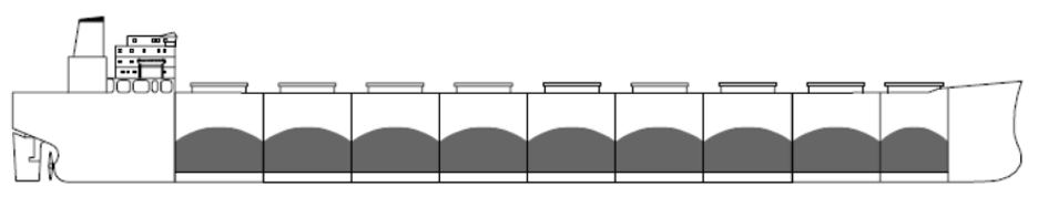
Structural failure is also affected by the type of cargo a ship carries and the way the cargo is carried aboard the ship. Less dense cargo is typically loaded homogenously as shown in the illustration below, with the cargo loaded evenly in across all holds.
Iron ore and other dense cargo are typically loaded in an alternate manner as shown below. This means that the cargo is only loaded into part of the holds. Because of the high density of iron ore, the holds are not filled to their maximum capacity.
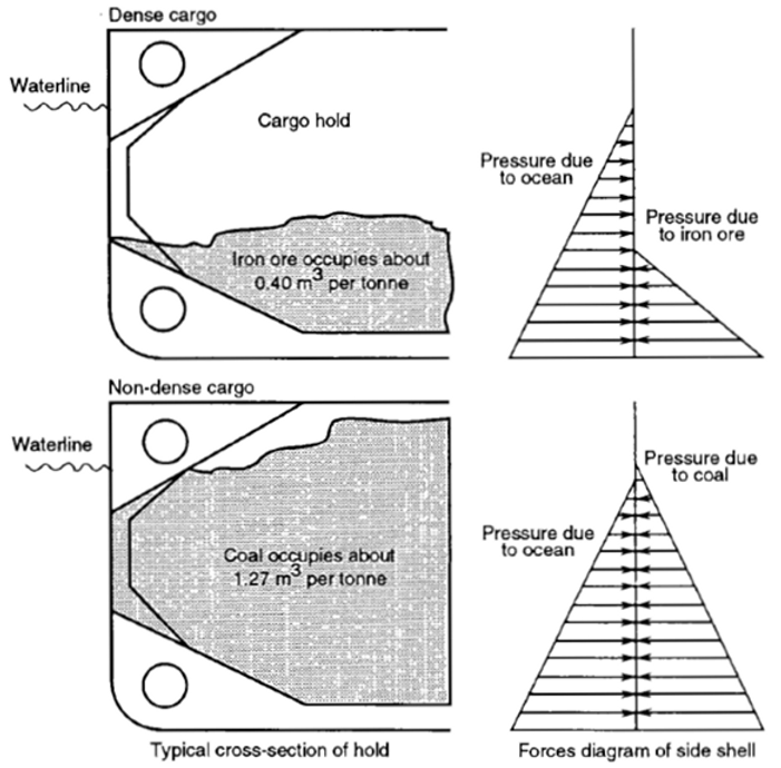
The cargo itself only exerts a force on a small section of the side plating as shown in the illustration above. This means that there is no force present to counteract the pressure from the water acting on the hull. The only resistance to the pressure is the strength of the hull structure itself. In less dense cargo, where holds are filled to the top, the two forces balance out, as seen in the lower part of the illustration. This means that the hull stress in ore carriers is typically greater than in ships carrying less dense cargo.
Loading Conditions
Structural damages to a ship may also occur due to loading and unloading conditions. Two factors play a key role: the speed at which the cargo is loaded onto the ship and whether the ship is designed for homogenous loading or for alternate loading.
If the cargo is loaded onto the ship very rapidly, the ballast system of the ship may not be ready yet to balance out the cargo and stresses in the ship may occur. If a ship designed for strict homogenous loading is suddenly loaded using alternate loading, structural failure may occur due to lack of strength to support the difference of forces in the holds. When the cargo holds of the ship are not loaded properly or when a hold takes on water and becomes flooded, shear failure is likely to occur at the bulkheads. If one hold is overloaded and the hold next to it is empty, a difference in forces occurs at the two holds. In the loaded hold, the forces from the load of the cargo are pushing down on the ship’s hull plates whereas in the empty hold next to it, the buoyancy forces are pushing up. This difference in force directions may cause shear to occur near the bulkhead.
Shear Forces and Bending Moments of the Hull Girder
Iron ore carriers are designed to withstand permissible still water shear forces (SWSF) and still water bending moments (SWBM) without encountering structural damage. The permissible SWSF and SWBM are different when the ship is docked in still water and when the ship is sailing out in open seas due to the higher dynamic loads experienced from waves in the open sea. If permissible SWSF and SWBM for both harbour and for seagoing conditions are exceeded, structural failure is likely to occur.
Loads on the Cargo Holds, Transverse Bulkheads and Bottom Plating
Ore carriers are designed to carry a specific load in each of their cargo holds, based on the draught of the ship, that should not be exceeded. Exceeding the recommended load for a given cargo hold will increase stresses in several key sections of the hold.
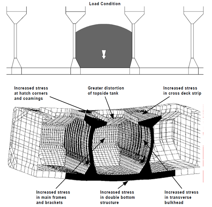
The sections of the hold shown in the illustration above, are all affected by the difference between the vertical forces acting down on the bottom plating and the buoyancy forces acting up on the bottom plating. This difference in forces is known as the vertical net load acting on the ship. The buoyancy forces acting upwards are directly related to the draught conditions of the ship.

As can be seen from the loading diagram above, when the draught is lower the specific cargo hold has a lower capability to carry cargo load. If the hold is overloaded under low draught conditions, an excessive net vertical load on the double bottom may occur, which in return may distort the structure of the hold as a whole.
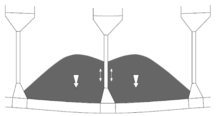
Symmetry of Loaded Cargo
Permissible SWSF and SWBM are both projected on the assumption that the cargo within each hold is symmetrically loaded, meaning it is evenly distributed and levelled. The diagram below shows an example of asymmetrically loaded cargo in two adjacent holds.
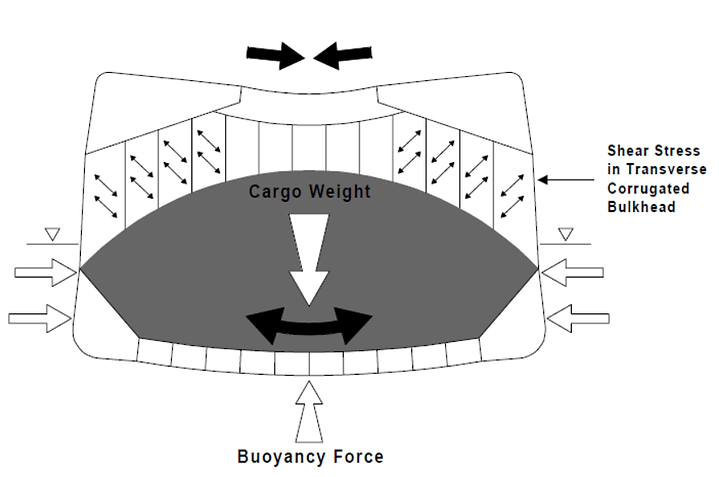
For dense cargo such as iron ore, this type of arrangement may cause excess stresses in the bottom plating, corners, and transverse bulkheads of the holds.

In the scenario of asymmetrical loading in two adjacent holds, shear buckling of the transverse bulkhead structure could occur as well as compression buckling of the cross deck and increased SWBM. This is because in such a scenario, a larger part of the vertical forces acting on the double bottom is transferred to the bulkhead between the two loaded holds. In addition, asymmetrical loading along the central axis of the ship´s cargo hold leads to loads causing torsion in the girder. The torsion forces may lead to cross deck shear and bending. Torsion may also occur due to asymmetrical ballasting and deballasting of tanks. Both asymmetric loading and asymmetric ballasting often result in hatch cracks and cross deck buckling caused by torsion.
If you found this topic interesting or if you have additional points to add from personal experience, please leave a comment below or get in touch with me!
The Shipyard